Wiring
Background Knowledge
Before diving too deeply into wiring, there is a slight bit of background knowledge to familiarize yourself with.
Binary & Binary Addition
Our "normal" counting system uses 10 digits: 0, 1, 2, 3, 4, 5, 6, 7, 8, 9. We will refer to this as Base-10. In Base-10, when you get to the last value in the list (9), you wrap around to first value (0) and increment the place to the left by one. For example:
9 + 1 = 10
Note that the above is equivalent to the following:
09 + 01 = 10
Binary is a simpler version of this. Binary is a system of counting that only has two digits it in, 0 and 1. So, when you would add two 1s together, you will get 0, much like how you get 0 when you add 9 and 1 in Base-10.
All binary numbers on this page will be given this prefix: b'
So in example, adding 1 and 1 in binary:
b'1 + b'1 = b'10
or, alternatively:
b'01 + b'01 = b'10
We add 1 and 1, which makes us loop around to 0. When we loop, we increment the place to the left by 1, just like in Base-10.
Here are some more addition examples:
b'0010 + b'0010 = b'0100
b'0100 + b'0001 = b'0101
b'0101 + b'0001 = b'0110
b'0110 + b'0010 = b'1000
In Starbound, signals will either be ON or OFF, which correspond to 1 and 0 in binary, respectively.
This is really all we will need for now, but if you want a more in-depth look at binary, the Wikipedia Article on it is a good starting point.
Inputs and Outputs
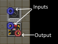
In Starbound, if you toggle Wire Mode (default hotkey "T") and look around, you will notice many different devices have red and blue nodes on them. Blue nodes function as signal(and/or power) inputs and red nodes are signal (or power) outputs. Note that for signal inputs, if at least one of the inputs to that blue node is ON, then the input node as a whole is considered as ON, even if not all the input wires are ON.
Generally speaking, if you scan an object (default hotkey "N", then click on it) you should get some insight into what the inputs and outputs of an object do.
Logic Gates
A Logic Gate is a device that, when given a combination of one or more input(s), will always output a particular value that is dependent on the input combination. The Wiring Table provides several recipes to craft logic gates for your use.
Truth Tables
A truth table is a table that shows all the possible input combinations and the corresponding output value of an object based on those inputs. We will use these to describe Logic Gates. See the tables in the next section for examples of Truth Tables.
Logic Gates Breakdown
NOT Gate
| Input | Output |
|---|---|
| 0 | 1 |
| 1 | 0 |
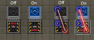
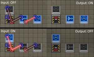
A NOT gate has only one input. A NOT gate takes and returns the inverse of the input (0 if 1, 1 if 0).
AND Gate
| Input 1 | Input 2 | Output |
|---|---|---|
| 0 | 0 | 0 |
| 0 | 1 | 0 |
| 1 | 0 | 0 |
| 1 | 1 | 1 |
| Input 1 | Input 2 | Input 3 | Output |
|---|---|---|---|
| 0 | 0 | 0 | 0 |
| 0 | 0 | 1 | 0 |
| 0 | 1 | 0 | 0 |
| 0 | 1 | 1 | 0 |
| 1 | 0 | 0 | 0 |
| 1 | 0 | 1 | 0 |
| 1 | 1 | 0 | 0 |
| 1 | 1 | 1 | 1 |
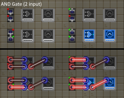
The AND gate takes 2 or more inputs and only returns ON if all inputs are also ON.
Common uses for AND gates are when you want to have several conditions met before doing something. IE: a Lightswitch that will only turn your lights on if it is night out.
OR Gate
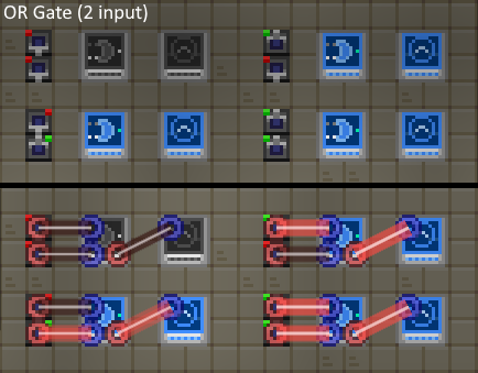
| Input 1 | Input 2 | Output |
|---|---|---|
| 0 | 0 | 0 |
| 0 | 1 | 1 |
| 1 | 0 | 1 |
| 1 | 1 | 1 |
| Input 1 | Input 2 | Input 3 | Output |
|---|---|---|---|
| 0 | 0 | 0 | 0 |
| 0 | 0 | 1 | 1 |
| 0 | 1 | 0 | 1 |
| 0 | 1 | 1 | 1 |
| 1 | 0 | 0 | 1 |
| 1 | 0 | 1 | 1 |
| 1 | 1 | 0 | 1 |
| 1 | 1 | 1 | 1 |
The OR gate takes 2 or more inputs and returns ON if at least one of its inputs is ON.
Common uses for standard OR gates are actually not too many, as the OR operation is implicitly done by blue input nodes (if any of the inputs to a blue node is ON, the blue node is treated as ON). However, OR gates can be used when you want to be explicit that your are OR'ing some inputs.
NAND Gate
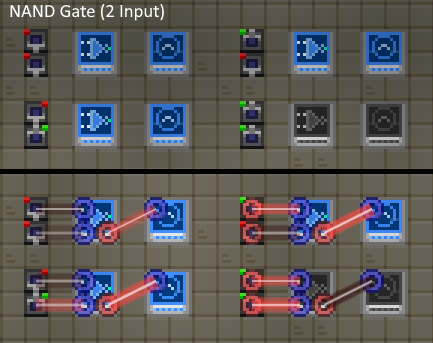
| Input 1 | Input 2 | Output |
|---|---|---|
| 0 | 0 | 1 |
| 0 | 1 | 1 |
| 1 | 0 | 1 |
| 1 | 1 | 0 |
| Input 1 | Input 2 | Input 3 | Output |
|---|---|---|---|
| 0 | 0 | 0 | 1 |
| 0 | 0 | 1 | 1 |
| 0 | 1 | 0 | 1 |
| 0 | 1 | 1 | 1 |
| 1 | 0 | 0 | 1 |
| 1 | 0 | 1 | 1 |
| 1 | 1 | 0 | 1 |
| 1 | 1 | 1 | 0 |
The NAND gate takes 2 or more inputs and only returns OFF if all inputs are ON. This gate is equivalent to an AND gate with a NOT gate attached to the output
NOR Gate
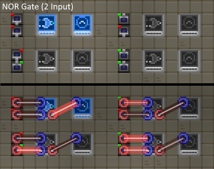
| Input 1 | Input 2 | Output |
|---|---|---|
| 0 | 0 | 1 |
| 0 | 1 | 0 |
| 1 | 0 | 0 |
| 1 | 1 | 0 |
| Input 1 | Input 2 | Input 3 | Output |
|---|---|---|---|
| 0 | 0 | 0 | 1 |
| 0 | 0 | 1 | 0 |
| 0 | 1 | 0 | 0 |
| 0 | 1 | 1 | 0 |
| 1 | 0 | 0 | 0 |
| 1 | 0 | 1 | 0 |
| 1 | 1 | 0 | 0 |
| 1 | 1 | 1 | 0 |
The NOR gate takes 2 or more inputs and returns OFF if at least one of its inputs is ON. This gate is equivalent to an OR gate with a NOT gate attached to the output
XOR Gate
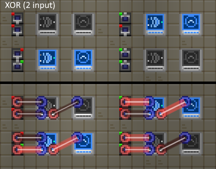
| Input 1 | Input 2 | Output |
|---|---|---|
| 0 | 0 | 0 |
| 0 | 1 | 1 |
| 1 | 0 | 1 |
| 1 | 1 | 0 |
| Input 1 | Input 2 | Input 3 | Output |
|---|---|---|---|
| 0 | 0 | 0 | 0 |
| 0 | 0 | 1 | 1 |
| 0 | 1 | 0 | 1 |
| 0 | 1 | 1 | 0 |
| 1 | 0 | 0 | 1 |
| 1 | 0 | 1 | 0 |
| 1 | 1 | 0 | 0 |
| 1 | 1 | 1 | 0 |
The XOR gate takes 2 or more inputs and returns ON if only one of its inputs is ON.
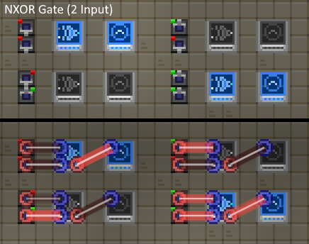
NXOR Gate
| Input 1 | Input 2 | Output |
|---|---|---|
| 0 | 0 | 1 |
| 0 | 1 | 0 |
| 1 | 0 | 0 |
| 1 | 1 | 1 |
| Input 1 | Input 2 | Input 3 | Output |
|---|---|---|---|
| 0 | 0 | 0 | 1 |
| 0 | 0 | 1 | 0 |
| 0 | 1 | 0 | 0 |
| 0 | 1 | 1 | 1 |
| 1 | 0 | 0 | 0 |
| 1 | 0 | 1 | 1 |
| 1 | 1 | 0 | 1 |
| 1 | 1 | 1 | 1 |
The NXOR gate takes 2 or more inputs and returns OFF if only one of its inputs is ON. This gate is equivalent to an XOR gate with a NOT gate attached to the output
Latches, Other Gates, and etc.
Master Logic Gate
This gadget has three input nodes on the left column and six output nodes on the middle and right columns.
This gate will simultaneously provide the output of the AND, NAND, OR, NOR, XOR, and NXOR operations applied to the signal 1 & signal 2 inputs.
The pin layout is such:
| Signal 1 | AND | NAND |
| CLK/Enable | OR | NOR |
| Signal 2 | XOR | NXOR |
This gate will update its outputs only if CLK/Enable is either not connected, or if that signal is ON.
This gate is useful when you need to run several logical operations on a pair of inputs.
Configurable 3-state cycler
This will cycle through 3 different outputs, with a user-defined duration at each step. To set this duration, place the cycler and then interact (Default key "E") with it to open a menu, edit the values, then hit save at the bottom.
The blue input node is an enable. If you toggle the enable from on to off, the cycler will cease all output and restart from input 1 when the enable is turned back on.
Sequencers
WIP
ITDs
SECTION IS WIP
Common ITD Uses
Automated Ore Smelting
WIP
Sift/Crush/Centrifuge/Extractor Queueing
Want to have stuff be processed without you manually putting items in the slots every time? You've come to the right place! This will show you how to make it so you have a drop-off box for stuff to put into a processor. The items in the box will be passed to the processor and the output will be stored in another chest.
To set up a Centrifuge, Crusher, Extractor, or Sifter for processing you will need the following:
- Two ITDs
- Two Storage Containers/chests
- Two storage bridges
- The Processing machine (Centrifuge, Crusher, Extractor, or sifter)
- Adequate Power for the processor
Now, to configure the setup:
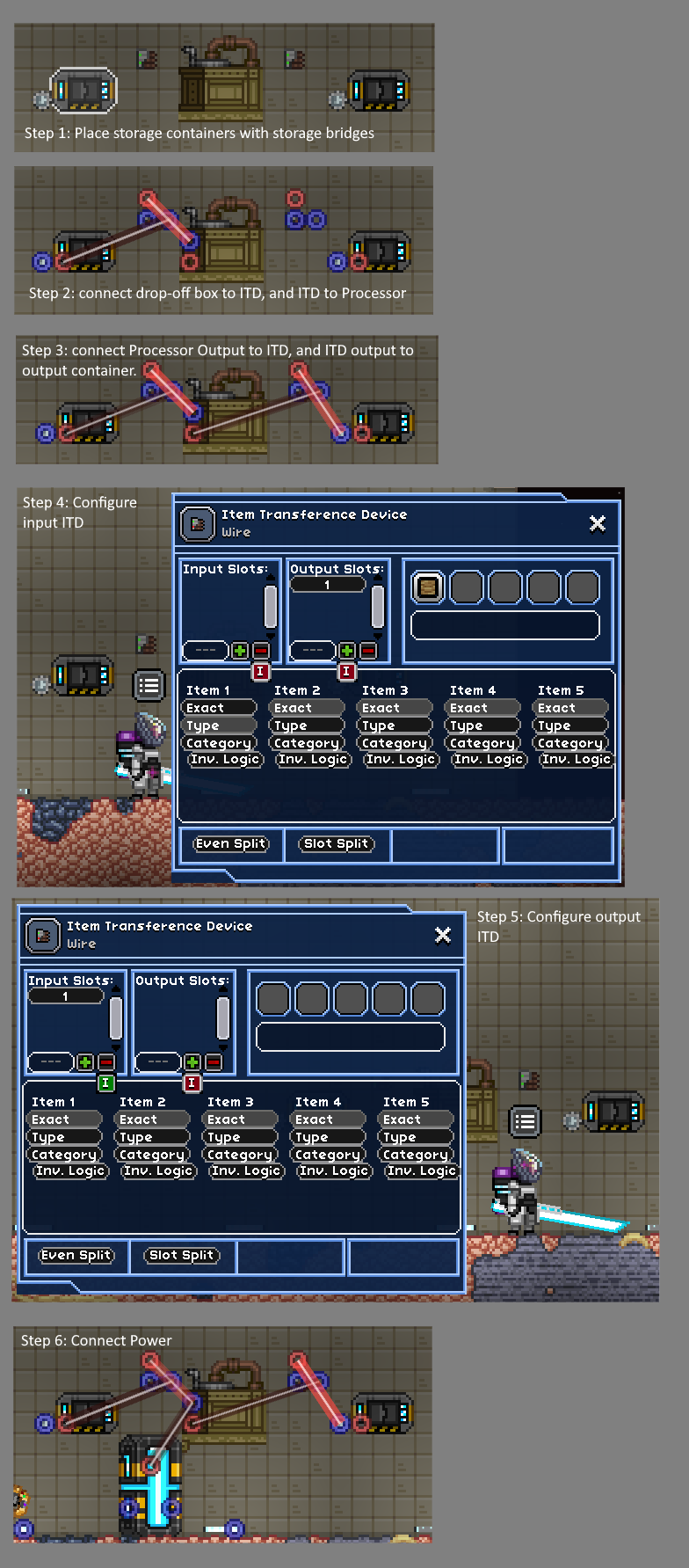
- Place the storage containers down with a storage bridge next to the bottom left corner of each container.
- Determine which chest you want to be the drop-off point for your item to be processed. Connect the output of this chest's storage bridge to the input node of an ITD.
- Connect the ITD's output node to the input node of the processing machine.
- Connect the output of the processing machine to the input of the other ITD
- Connect the second ITD's output node to the input node of the output chest's storage bridge.
- Open up the first ITD and set the output slots to the input slots used by the processor (For details on the slots to designate, see the Input slots per Processor table below.)
- Put an item of the type you want to pull out of the first container (block, liquid, etc.) in the leftmost item slot of the ITD.
- Click on the "Type" button in the Item 1 column of the ITD interface (should be a light gray color when selected)
- For the second ITD, exclude the input slots of the processor by entering the same numbers you did for the other ITD, then click on the Red "I" box below the input slots column. (It should turn from red to green)
- Finally, connect your power to the input slot of the processor and give the system a try!
| Extraction Station | Input slot #s | Input Type |
|---|---|---|
| Hand Mill | 1,2,3 | all |
| Extraction Lab | 1,2,3 | all |
| Extraction Lab MKII | 1,2,3 | all |
| Quantum Extractor | 1,2,3 | all |
| Sprouting Table | 1,2,3 | Seeds & Plants |
| Xeno Research Lab | 1,2,3 | Seeds & Plants |
| Advanced Xenolab | 1,2,3 | Seeds & Plants |
| Rock Breaker | 1 | Rocks, stone & crystal blocks |
| Rock Crusher | 1 | Rocks, stone & crystal blocks |
| Sifter | 1 | granulars |
| Powder Sifter | 1,2 | granulars |
| Wooden Centrifuge | 1 | Milk, Water, Contaminated Water and Combs |
| Iron Centrifuge | 1 | Milk, Fluids and Combs |
| Industrial Centrifuge | 1,2 | Milk, Fluids and Combs |
| Lab Centrifuge | 1,2,3 | Milk, Fluids and Combs |
| Gas Centrifuge | 1,2,3,4 | Milk, Fluids, Isotopes and Combs |
Power
WIP
Liquid Movers
WIP

